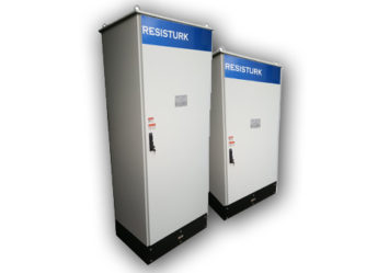
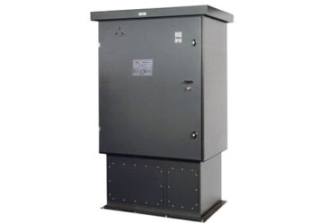
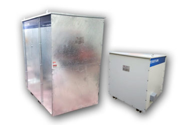
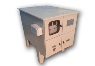
» HIGH RESISTANCE NEUTRAL GROUNDING RESISTORS
+90 0850 441 0591
entrdeares
Our Social Media Accounts

HIGH RESISTANCE NEUTRAL GROUNDING RESISTORS

HIGH RESISTANCE NEUTRAL GROUNDING RESISTORS

High Resistance Neutral Grounding
High Resistance Neutral Grounding Resistors
In phase-to-ground faults that occur in networks up to 5000V, the continuity of the operating is one of the most important issues, besides the safety of personnel.


In High Resistance Grounding Systems, High valued resistance is connected between transformer or generator neutral and ground. In this way, the fault current is limited to the desired small current value. (Artificial neutral point in triangular connected networks without neutral lines, created with “Zig-Zag transformer” or “open triangular grounding transformer”)

By limiting the earth fault current to a small current value, it is ensured that the operation of the operator is continuous during the fault and the location of the fault is made easier

General
  • Designed and tested with IEEE 32-1972
  • All stainless steel resistor elements
  • All parts factory assembled.
  • Meets sismic zone 2 requirements
  • Epoxy based electrostatic powder painted hot-dip galvanised or stainless stain enclosure
  • Solid-Steel one-piece top
  • Folklift friendly legs and lifting lugs


APPLICATIONS

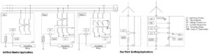
HRNGR Artifical Neutral Point Creation Sample

TECHNICAL DESCRIPTION

When a fault occurs in a system with High Resistance Grounding, the Resistance begins to limit the fault current. (typically between 2A and 10A) During the fault, the large resistance grounding resistor injects current into the network at 1 second intervals with the current injection system. The staff follows the current with a pens ammeter. It follows the current to the point where the current is gone and finds the fault.

Fault currents are usually limited to between 2A and 10A. In case of malfunction, notice information, warning siren and RS485 output interface failure recorder (Logger) can be included in the High Resistance neutral ground resistance panel.


TECHNICAL SPECIFICATIONS

  • Operation Voltage            : Up to 5000V
  • Rated Current                   : 2A to 10A
  • Ambient Temperature     : -40 to +55DegC
  • Protection Degree           : IP00 to IP55
  • Resistor Element             : Stainless Steel or SS Alloy
  • Enclosure                          : 2mm hot-dip Galv SS- steel
  • Color                                   : All RAL Colors Avalibe
  • Special Requirements : Ex-Proof / Atex Std. Production Avalibe ,
Additional Options:
  • Analog Voltmeter (0-10A) – Analog Voltmeter (0-5000V)
  • Pulse / Normal Current Selector Switch
  • Grounding Fault Light / Buzzer
  • Logger (RS485 Output)
  • Dry Output Contacts
 STANDARTS:
IEEE 32, IEC60137,  EN10346, ISO129 44, IEC60071, IEC60060, IEC60529,IEC60273, ISO-EN 1461,

Ex-proof Standards:

EX-Proof Neutral Grounding Resistors  are manufacture according to following Eex standards
Eex d – IEC 60 079-1, Eex e – IEC 60 079-7, Eex i -IEC 60 079-11 – Eex q – IEC 60 079-5 , Eex n – IEC 60 079-15
ADDITIONAL OPTIONS

Neutral grounding resistors can be manufactured with many additional options according to the type of application used.

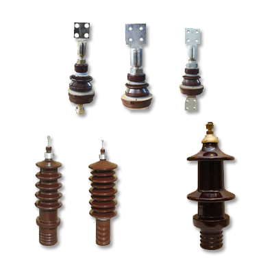
Current Transformer and Voltage Transformer:
Primer or secondary is used for measurement or protection. (can be produced at the desired value).
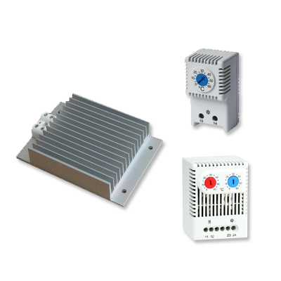
 

Panel Heaters:
They are used to protect the internal panel of resistance against very cold environments. They are produced at the desired voltage level.